

Steps 10a to 10c: Pointing devices
Use one pointing device per half. Every FFC connection follows the same order: unlatch, insert, latch (see Step 6).
10a TrackPoint
Section titled “10a TrackPoint”- Attach a same-side FFC to the TrackPoint: unlatch, insert the contacts up, latch.
- Mount the TrackPoint in its holder with the M2 thread-cutting screws. Attach the cover.
- Route the cable with the finger cluster cables (Step 10).
- This half needs TrackPoint firmware. See Step 15.
- The TrackPoint half must be the half you connect to your computer (Step 15).
10b Trackball
Section titled “10b Trackball”Trackball holder
Section titled “Trackball holder”- Print the holder at 0.2 mm layer height with 6 or more walls. You can add supports under the large bridges, but in PLA the holders work fine without them.
- The holder takes four static bearing balls, 3.175 mm. Some older holder designs use 3 mm balls. See Trackballs and static bearings.
- Remove the supports. Make sure the ball cavities are clear of stray material.
- Put a small drop of medium CA glue in each bearing location, and drop a bearing into each.
- After a moment, press each bearing into its seat with a screwdriver blade, so it seats fully.
- Test the ball fit. The top arm (the keeper) should be very close to the ball but not touch it in normal use: 0 to 0.2 mm.
- If needed, heat the keeper and bend it slightly to get the hold you want. Use hot water for PLA, or a heat gun on low for ABS. This is easier before the sensor is installed.
If you don’t carry your Svalboard around and don’t tent it steeply, you don’t strictly need the keeper.
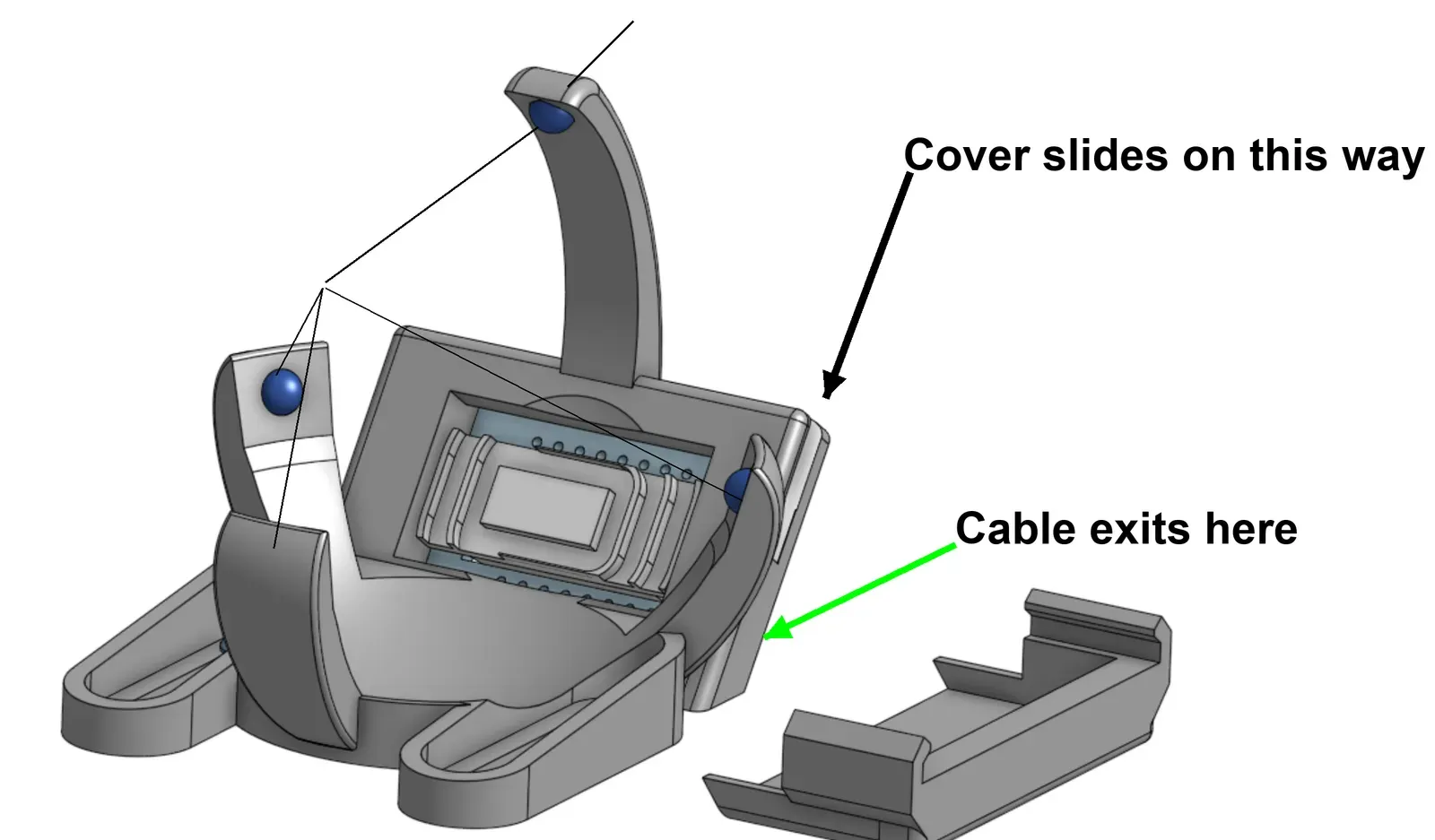
Trackball PCBA
Section titled “Trackball PCBA”- Attach a same-side FFC to the trackball PCBA: unlatch, insert the contacts down, latch.
- Check which sensor the PCBA has. You need this to pick the firmware in Step 15.
- Current PCBAs use the PMW3389.
- Older PCBAs may use the PMW3360 (deprecated).
- Look for silver marker on the PCBA, or read the tiny text on the sensor itself.
- Flashing the wrong image does no harm.
- Mount the trackball PCBA in its holder with the M2 thread-cutting screws. Attach the cover.
- Route the cable with the finger cluster cables (Step 10).
- Connect the trackball cable to the 8-pin FFC connector marked “TrkPt”, “Trackball” or “Ball”, depending on your MCU: unlatch, insert the contacts down, latch.
On vNext1 you can skip the sensor check. The firmware detects both sensors.
10c Touchpad
Section titled “10c Touchpad”- The touchpad uses the same mounting rail as the trackball, so you can swap them.
- It needs MCU v3.1 or newer.
- Connect the 6-pin FFC to the touchpad: unlatch, insert the contacts down, latch.
- Connect the other end to the 6-pin “Azo” connector on the MCU: unlatch, insert the contacts down, latch.
- Mount the touchpad on the rail.
- Route the cable with the finger cluster cables (Step 10).
- This half needs touchpad firmware. See Step 15.