

Step 1: Print all parts
Get the files
Section titled “Get the files”The parts are in the svalboard-self-print repository. If you don’t have access yet, ask @claussen on the Svalboard Discord.
Which version to print
Section titled “Which version to print”- In general, use the latest version.
- V2.0 greatly improves the key mechanism tolerances. Use it unless you’re building to match older printed parts.
- Keys and clusters must come from the same major version, or they won’t fit together.
- Many other parts didn’t change from V1.3 to V2.0 and were carried forward as they are.
- The repository may hold prototypes or parts that aren’t in your kit. If you’re unsure whether a part fits, ask in #supporters on Discord.
What to print
Section titled “What to print”Pick your side key size first. See Sizing before you build.
Finger keys
- 8 North keys: 11 mm tall, Thick (16 mm), medium force (0.7 mm offset).
- 24 East, South and West side keys: 6 mm tall, in your size: Thick (16 mm), Semi (17 mm), Thin (18 mm) or Backset (20 mm). Medium force (0.7 mm offset).
- 8 tipping center keys: 0.9 mm offset is a good starting point.
Thumb keys
- 2 Pad, 2 Knuckle, 2 Down, Nail Left, Nail Right, and 2 Up (Mode) keys.
Clusters
- 8 finger clusters
- Thumb L and Thumb R
Other parts
- Palm rests and carriers: Left Palm Rest, Right Palm Rest, Left Carrier, Right Carrier.
- Base plates and cases: L Base, L Case, R Base, R Case.
- TrackPoint case, if you have a TrackPoint: top cover and bottom cover.
- Tools: mini 4x3 magnet stages (Key and Cluster), magnet dropper, mini key tray fixture.
Print tuning
Section titled “Print tuning”- Use a smooth or satin build plate. Fully textured plates make the parts look rough. This is only about looks. We recommend the Fabreeko HoneyBadger SemiSatin plate.
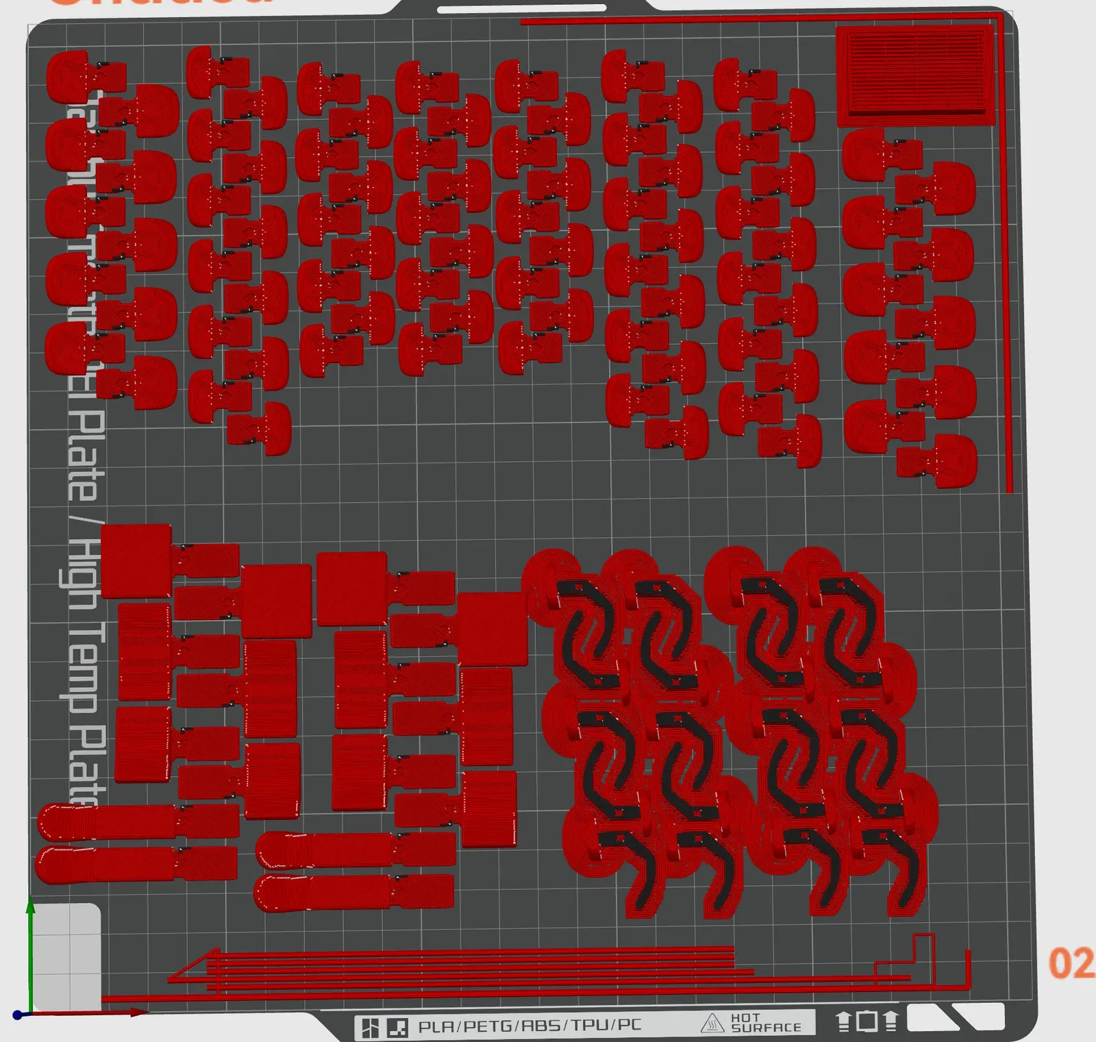
- Only the palm rests and the tipping center keys need supports.
- Start by getting the 6 mm side key perfect, then the finger and thumb clusters. If you can print those, the rest is easy.
- PLA: 0.12 mm layer height, 0.18 mm first layer.
- ABS: the same settings work, but the filament must be very dry. ABS is finicky with overhangs if it’s even a little damp.
- Exterior perimeters: 0.3 mm.
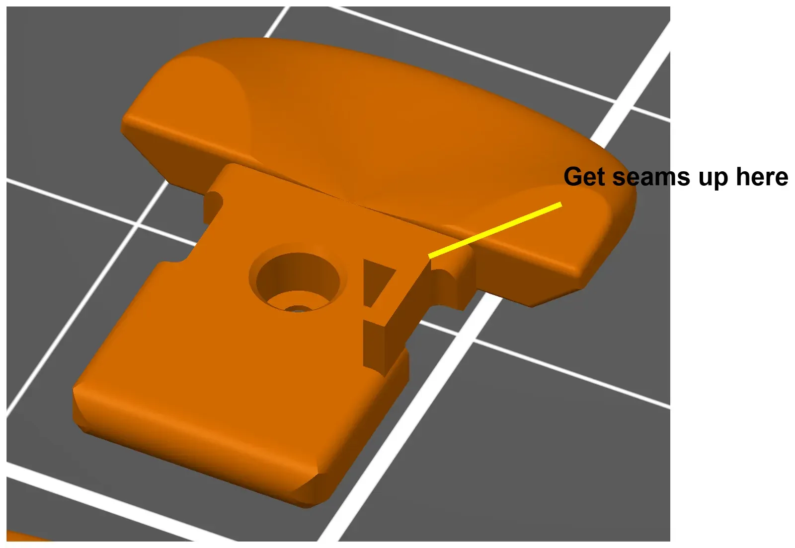
- You may need to paint seam blockers on the sides of the small flag on each key.
Key flags
Section titled “Key flags”The flag is the thin tab under each key that blocks the optical sensor.
- If flags form badly, place the seams at the top corner of the flag. Seams on the flag face can leave pinholes and heat artifacts that let light through.
- The flags must be about 0.8 mm thick or less for the parts to fit. With a 0.4 mm nozzle, set exterior perimeters (“outer wall” in Orca and Bambu Studio) to 0.3 mm.
- You may still need to clean up stringing. Slower printers and wet filament make stringing worse.
- If your filament isn’t opaque to infrared light, coat the flags with opaque marker. Silver Sharpie works well (Step 5).
Key force
Section titled “Key force”The offset sets how hard a key is to press. A larger offset gives a lighter key.
Tipping center keys
Section titled “Tipping center keys”The tipping center key is the standard center key. The default strength is 0.9 mm offset, about 20 g. The STEP file has every offset from 0 to 1.2 mm (very light) if you want to experiment.
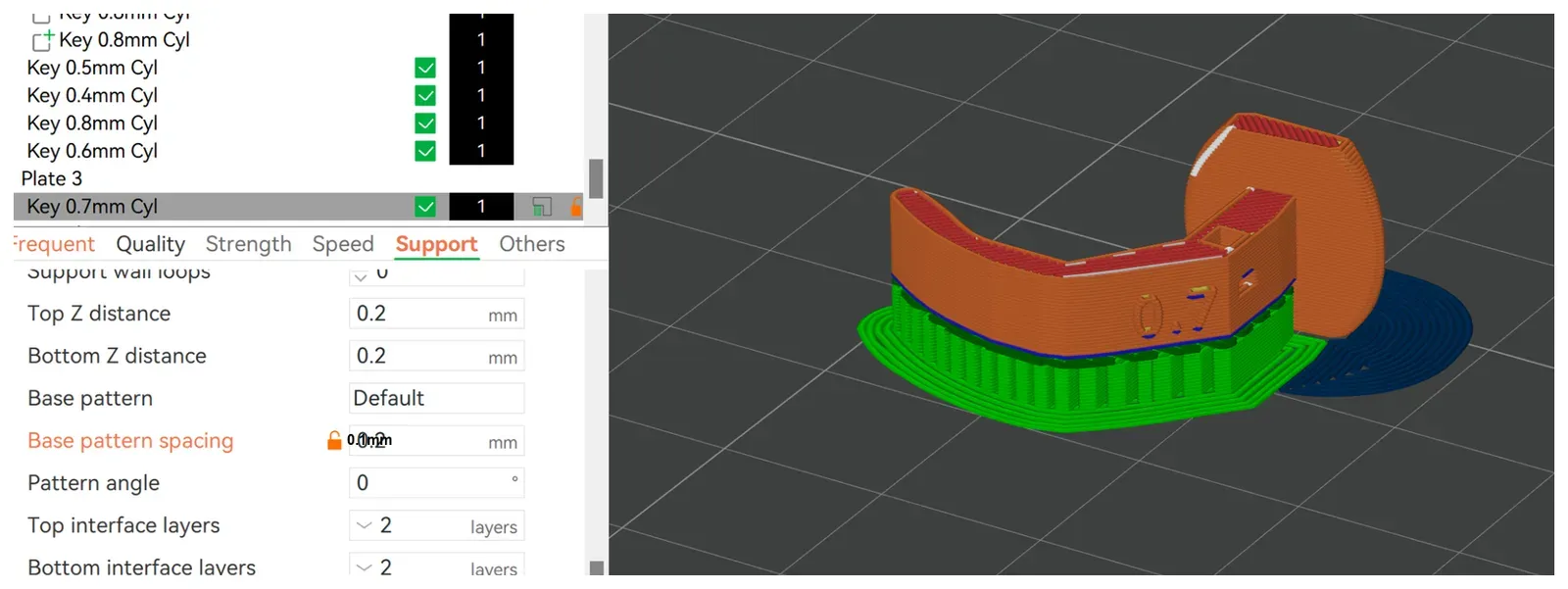
- Print at 0.2 mm layer height.
- Make the supports very dense: 0 or 0.1 mm base pattern spacing, and zero interface layer spacing (a very dense support interface).
- Dense supports come off as one block and leave a clean surface, so you have little or no cleanup inside the light hole.
Clusters
Section titled “Clusters”- 0.2 mm layer height.
- Arachne on is recommended.
- The tipping center key clusters don’t need supports.
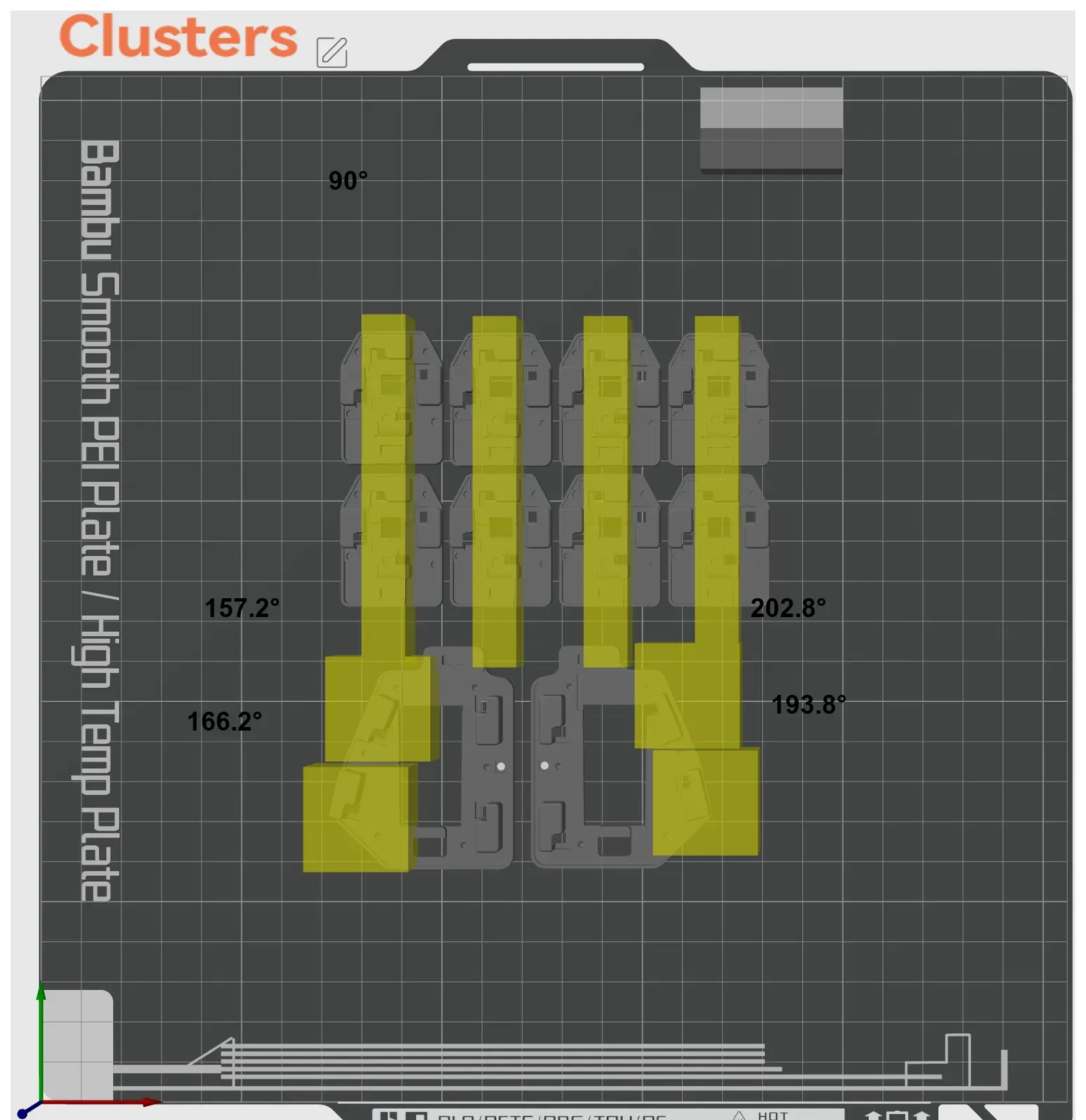
- V2 and later: bridging angle 0 (automatic).
- V1.3 and earlier: bridging angle 180°, plus bridging modifiers at the angles shown below.
- If your printer can print two colors, print the small diffusers for the RGB layer lights in white.
Thumb Down key opening
Section titled “Thumb Down key opening”The marked edge of the thumb cluster must be square. Elephant’s foot here makes the thumb Down key bind. A bevel here can add play to the key and change how it feels.
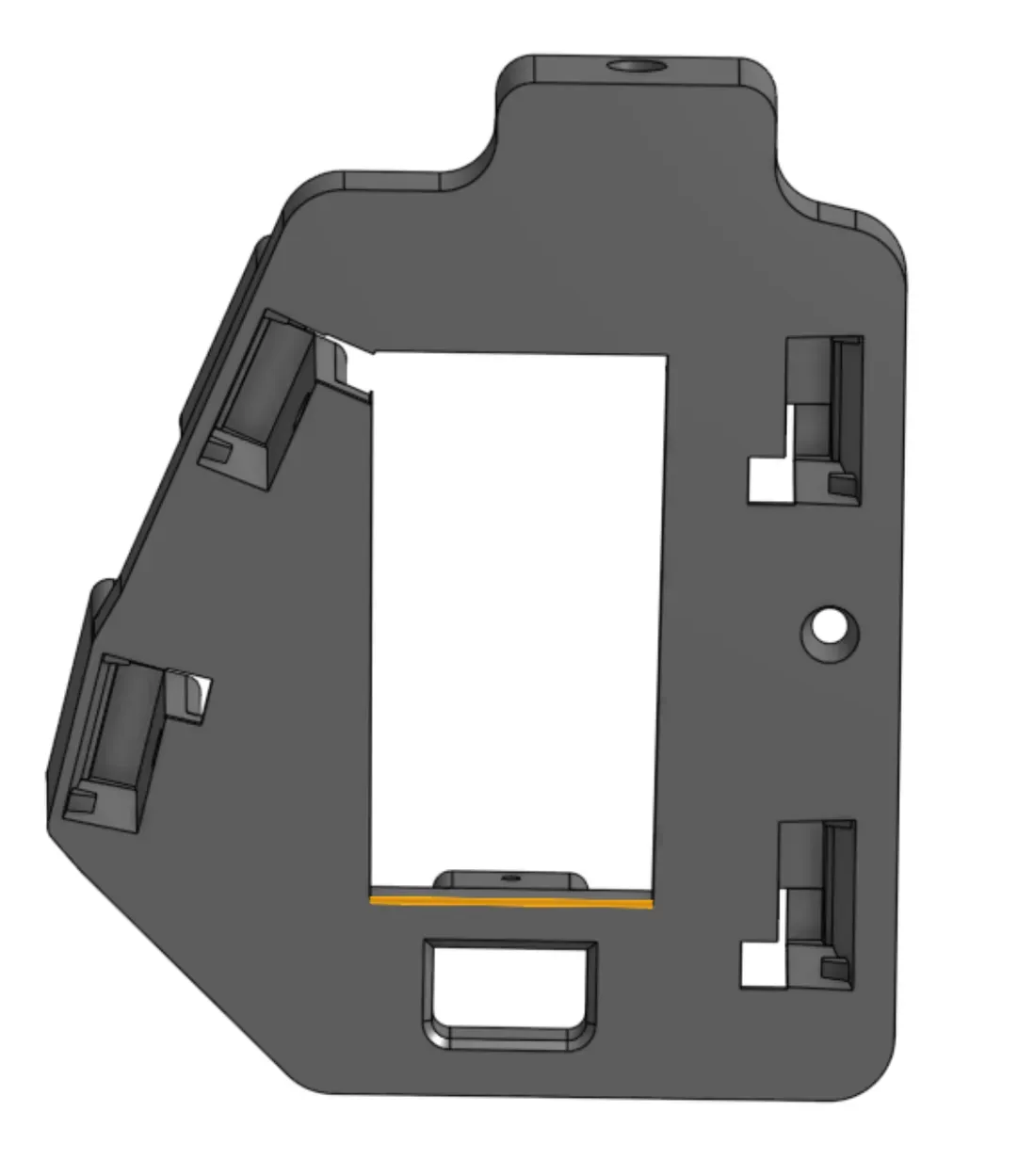
Cases and base plates
Section titled “Cases and base plates”- 0.2 mm layer height, 6 walls.
- Default bridging angle 180°.
- Bridging modifiers in the slot areas, as shown.
- Smooth side down.
- No supports.
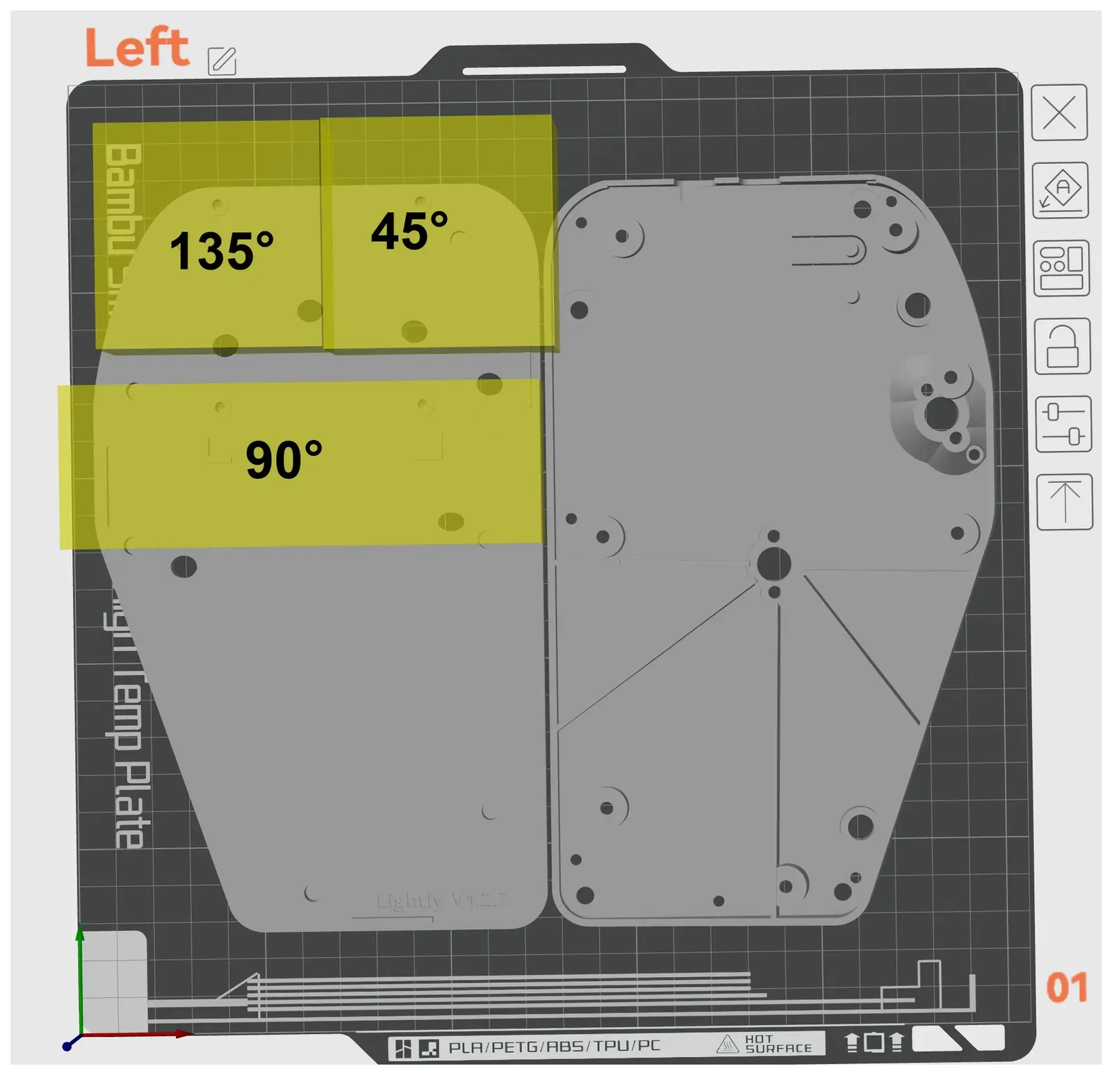
Palm rests and carriers
Section titled “Palm rests and carriers”- Use tree supports (Auto, Default or Organic) for the palm rests.
- Stand each palm rest on the flat long edge made for this.
- Add a brim to the palm rests. You may want to paint seam blockers on the visible surfaces.
- No supports on the carriers or shims.
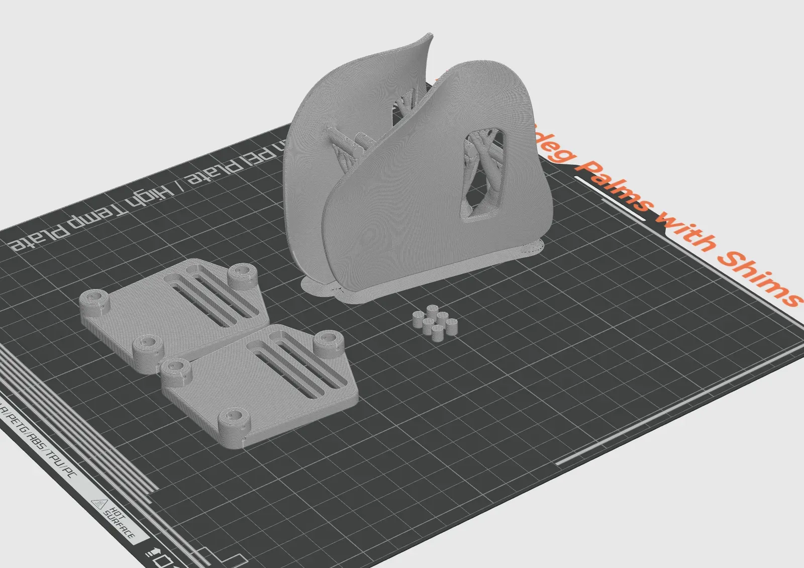
TrackPoint case
Section titled “TrackPoint case”- 0.2 mm layer height.
- Flat sides down.
- No supports.
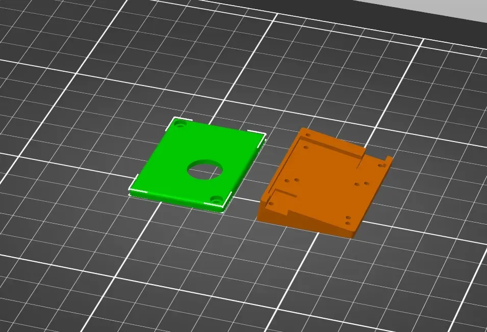
Deprecated parts
Section titled “Deprecated parts”Don’t print the center key sliders (gap sliders) or the printed towers. The tipping center keys and clusters replace the sliders, and the kit includes stainless steel towers.