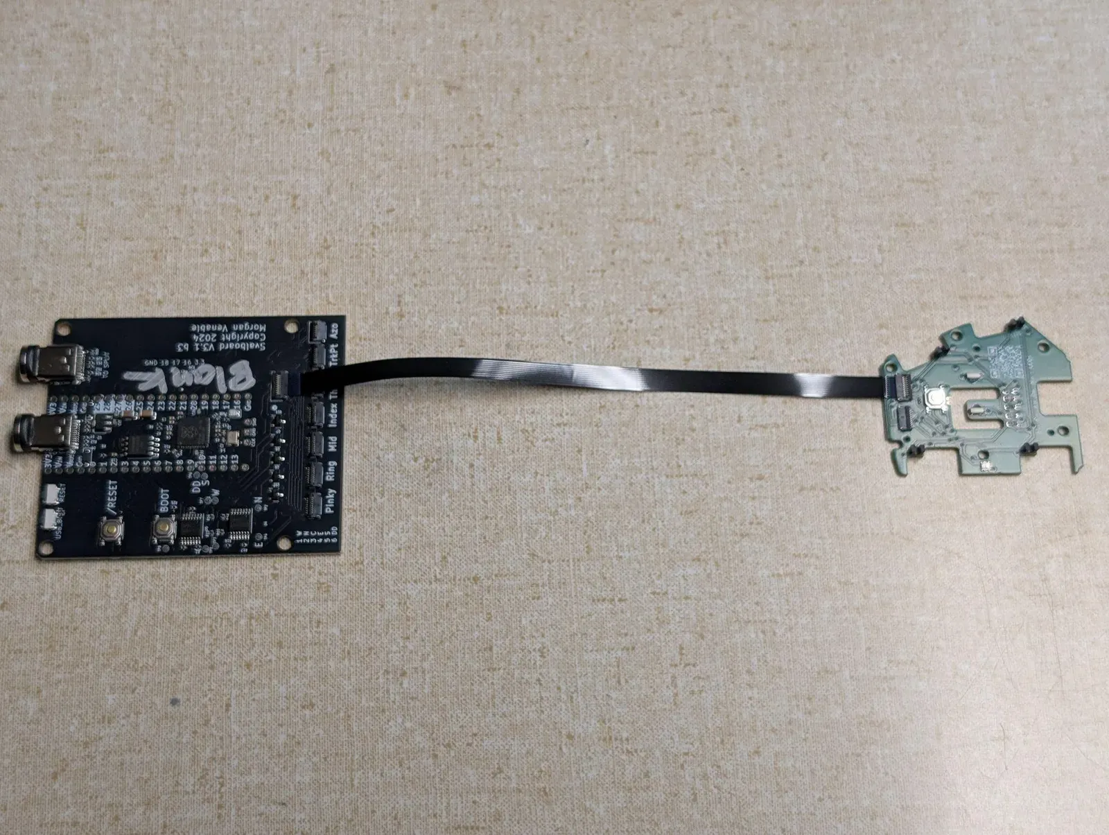
Step 6: Attach FFCs
Every FFC connection
Section titled “Every FFC connection”Every time you connect an FFC, do it in this order:
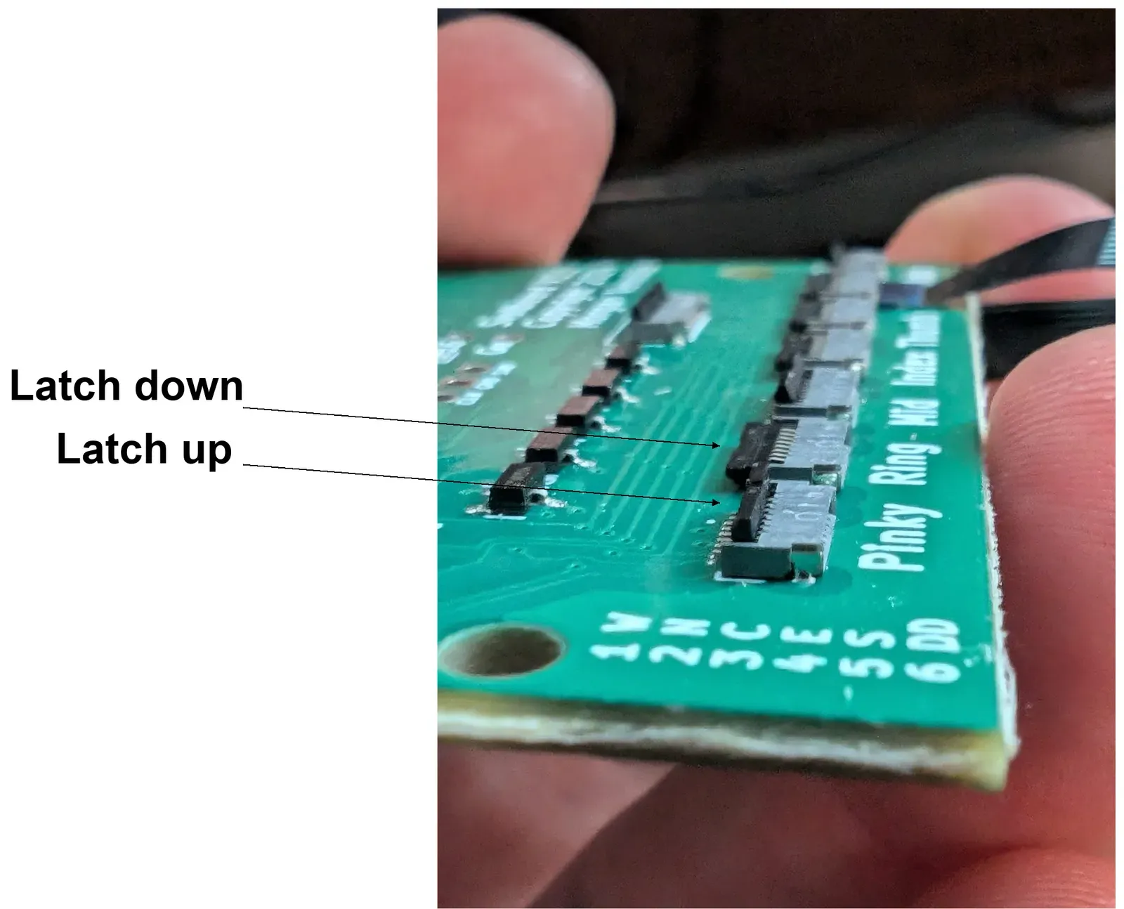
- Unlatch: flip the connector’s black latch up.
- Insert: slide the FFC fully into the connector, with its contacts facing the way the step says.
- Latch: flip the latch down to lock the FFC.
To remove an FFC, reverse it: unlatch, pull the FFC straight out, then latch the empty connector.
Contacts face down at both ends of every FFC, with the blue stiffener up. The one exception is the TrackPoint PCBA end, where the contacts face up.
Attach FFCs to the PCBAs
Section titled “Attach FFCs to the PCBAs”- For the thumbs, use only the 10-pin FFC if you have it. The RGB layer lights need it. The 8-pin thumb connector on the MCU is for older builds only.
- Unlatch: flip the black latch up.
- Insert the FFC with the contacts down and the blue stiffener up.
- Latch: flip the latch down to lock it.
- On thumb PCBAs, route the cable down through the slot after you close the latch.
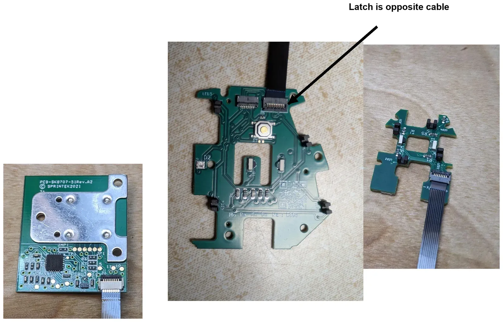
- The latch is on the side opposite the cable.
- Exception: on the TrackPoint PCBA the contacts face up (Step 10a).
FFCs on the MCU
Section titled “FFCs on the MCU”You connect the other end of each FFC to the MCU in Step 12. The same rules apply:
- For the thumbs, use only the 10-pin FFC if you have it. The RGB layer lights need it. The 8-pin thumb connector on the MCU is for older builds only.
- At each MCU connector: unlatch, insert the FFC contacts down, latch.